Understanding HD44780 compatible LCD-displays
ArticleCategory: [Choose a category, translators: do not
translate this, see list below for available categories]
Hardware
AuthorImage:[Here we need a little image from you]
![[jan.svenungson]](../../common/images/jan.svenungson.png)
TranslationInfo:[Author + translation history. mailto: or
http://homepage]
original in en Jan
Svenungson
AboutTheAuthor:[A small biography about the author]
Jan has been using GNU/Linux since 1996 and has had 2
unintentional re-boots since then (not counting re-boots due to
power failures).
Abstract:[Here you write a little summary]
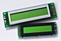
This article is trying to teach you a thing or two about the
HD44780 compatible LCD-display.
We will go through how to connect it to your parallel port and
how to program it with a small program called LCDInfo as a
reference.
You're not supposed to just connect the display, run a
program and get all you need on the display but also
understand how the hardware can do what you want.
ArticleIllustration:[One image that will end up at the top
of the article]
![[HD44780]](../../common/images/article258/lcdandtux.gif)
ArticleBody:[The main part of the article]
Introduction
First, you need to get some hardware and software, I
assume you already have a computer with a standard
parallel (printer) port on which you can run GNU/Linux with gcc
and glibc.
You will also need a LCD display which is HD44780
compatible, cables to connect this to your parallel port and
also a potentiometer if you want to change the contrast. To
power the display you will most certainly need more juice than
your parallel port will give you and you might need to get the
power from somewhere else in your computer. The best way to do
this is by using a standard +5V connection (the ones used to
power disk-drives, hard-drives, etc).
When you have connected the LCD display you need to know how it
works. This is what usually is left out in other articles on
the subject but I will try to explain some of the internals of
the display which will help you program it.
The last thing to do is to actually make the display print
something useful. As a reference I will use a small program
called LCDInfo which has support for most features of the
HD44780 but doesn't print much at the moment. This program is
alpha and I work on it when I have spare time.
If you have never programmed C before you might want to
consider reading a bit on C, I assume you are a beginner in
C since that is my current level.
How to connect it
![[schematic]](../../common/images/article258/ParportToHD44780_th.png) First,
let's look at the different pins available on the LCD and
explain what they do.
First,
let's look at the different pins available on the LCD and
explain what they do.
Pin 1 is called VSS and is supposed to go to GND.
Pin 2 is called VDD and this is the power supply pin which is
at +5V.
Pin 3 is called VLC and is connected to the potentiometer to
decide the contrast of the display.
Pin 4 is the RS pin and depending on this pin the display
prepares to get instructions or data.
Pin 5 is the R/W pin and this controls whether the LCD is
sending or receiving.
Pin 6 is the Enable pin. When this goes from low to high and
then to low again the LCD reads pins 4,5 and 7-14.
Pins 7-14 are the data bus line called DB0-DB7, these
are the main data bits sent to the LCD and controls where and
what to be written on the display.
Pins 15 and 16 are only present on displays with back lighting
and are simply +5V and GND with a 3.8 Ohm resistor between pin
15 and +5V.
To find out where you should connect these on the printer port
you can look at the schematic on the right where i have tried
to make this as clear as possible. Click on the schematic
diagram for a bigger picture.
This schematic only applies if you want to change the contrast
of the display. I simply connected pin 3 and pin 1 to GND which
works OK for me, if you have strange lighting in the room you
might want to consider adding the potentiometer though.
When getting the power from the PC please be careful. If you
take the power from the wrong cable you will get +12V which
will fry your LCD. The cable you want is the red one. Yellow is
+12V and black is GND.
If you have done this right the LCD should have the first (and
third if it exists) row black when you turn on the PC.
How the LCD works
The LCD doesn't do anything until you tell it to, it simply waits
until it gets a valid enable rise and fall (which is when we
put the enable pin high, wait for a while and then put the pin
back low). At this point the display reads whether it is
instructions or data to be processed, then whether it will
receive or send information and last the data bits are sent or
received.
In this article we will never receive information from the LCD
so the R/W pin will always be low which means write.
The RS pin will be low except for when we print characters,
everything else is considered instructions.
This makes it really simple to program the display.
When we know this we want to start with turning the display on
and make it ready to receive information. This is done in the
initialization sequence where we tell the display to be turned
on, which "function set" to use, etc.
The power should already be on if you get the power from a
spare power cable in the PC, otherwise this is the first thing
to do.
Next is the "Function set" which is dependent on what display
you have.
To make it more easy to understand I will explain exactly what
we do when we use the function set.
DB2 is the Character Font bit and this should be
low meaning 5x7 dot matrix.
DB3 is the Display Lines bit and should be high
meaning 2 lines. What if you have 4 lines on the display? Don't
worry, the first and third line are the same in the display
memory so you should use high to.
DB4 is the Data Length bit and this decides if you have
4 or 8 DB, if you connect the display according to my
schematics you should have this DB high.
Then set DB5 high to tell the display that this is
indeed a "Function Set" instruction, then make sure that
RS and R/W is low and do a enable rise and
fall. For timings check the manual, i assume we only pause for
microseconds when waiting for the display which should be much
more than needed.
What about the code?
Here I will discuss the parts of the LCDInfo program which you
need to understand how the interface of the HD44780 works. You
can download the LCDInfo program at the end of the article or
take directly a look at of the c-code files iolcd.c and lcdinfo.c by
clicking here.
What we need now is the above instructions written in C and
believe me when i say its easy. I will go through the code step
by step and even if you are a C beginner you will
understand.
First of all we include some header files and define functions
(check the source for info). Then comes the fun part.
#define D_REGISTER 0
#define I_REGISTER 2
#define WRITE_DATA 8
#define BASE 0x378

int main(void)
{
  ioperm(BASE,3,1);
  [CUT]
}
This is the first instruction in the main function which gives
us permissions to the parallel port. BASE should be 0x378 or
something and the "3" part means we have access to 0x378, 0x379
and 0x380 which basically is the whole printer port.
The reason there are three addresses is because the port is
divided between data, status and control. For us this means we
have to set the data pins first, the control pins second and we
cannot do this in one command.
Next thing to do is the function set described above.
void function_set(void)
{
  outb(56, BASE);
This sets the DB pins to 5x7 dot matrix, two lines etc.
outb(I_REGISTER + WRITE_DATA, BASE + 2);
This sets the RS and R/W pins to instruction and write. I have
made global variables of I_REGISTER and WRITE_DATA and they
equal 2 and 8.
Next is the enable rise and fall.
  outb(ENABLE + I_REGISTER + WRITE_DATA, BASE + 2);
  usleep(0);
  outb(I_REGISTER + WRITE_DATA, BASE + 2);
}
What this code does is basically puts the enable to high, wait
and put the enable to low. The command for the usleep(0); is
not really ideal but i have not finished the timing code for
the display.
Quite a few of you might wonder why I turn the RS and R/W
on in the code when I say that they should be put low in
the instructions. This is because pins 1, 14 and 17 are
"hardware inverted" meaning that if pin 14 is "off" as far as
the printer port is concerned, the pin is high!
Well, I told you it was easy, didn't I?
How to get characters displayed
Maybe you want to have some practical use for your display
also, like displaying text? No problem.
The code (code as in commands) is identical to printing a
character and to setting the functions. The only thing we need
to do is change some variables. We do not want the RS set to
instruction but to data to start with. This makes the function
print_character() look like this:
void print_character(int character)
{
  outb(D_REGISTER + WRITE_DATA, BASE + 2);
  outb(character, BASE);
  outb(ENABLE + D_REGISTER + WRITE_DATA, BASE + 2);
  usleep(0);
  outb(D_REGISTER + WRITE_DATA, BASE + 2);
}
As you can see we changed "I_REGISTER" to "D_REGISTER" and "56"
to "character" but what does this mean? If you look at the
character codes in your manual you will understand.
We only need to feed the function a character (since we use C
we do not even have to bother making it an integer first) and
then the character will pop up on the display. Neat, huh?
With this code you have the bare bones of an LCD program, use
it to fit your needs, display free mem, display active http
connections or whatever. Some examples are in the LCDInfo program
which displays some things available in the proc filesystem on
a GNU/Linux computer.
References
![[schematic]](../../common/images/article258/ParportToHD44780.png) First,
let's look at the different pins available on the LCD and
explain what they do.
First,
let's look at the different pins available on the LCD and
explain what they do.